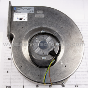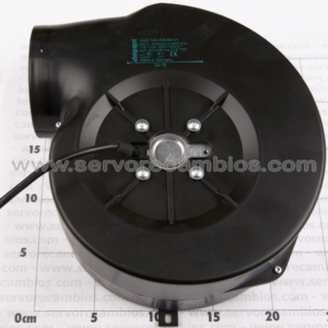
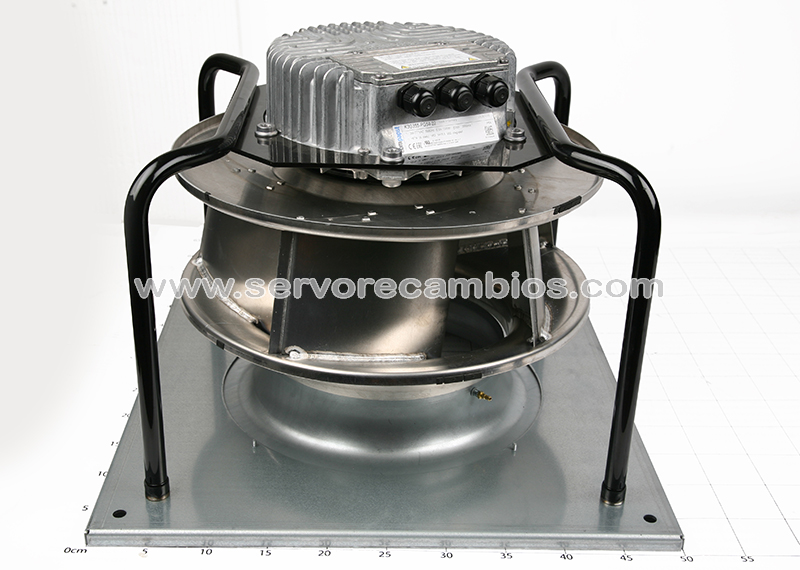
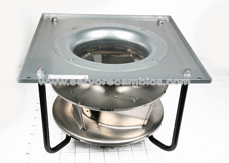
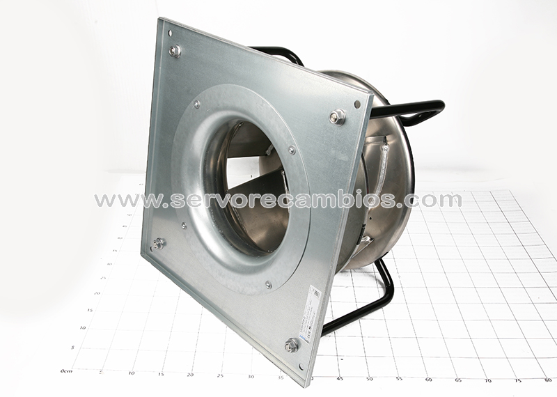
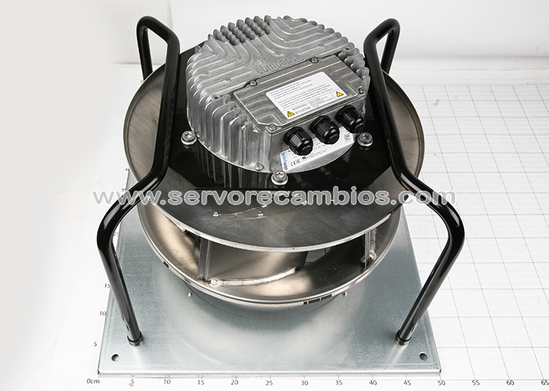
Type K3G355-PG54-22
Motor M3G112-EA
Phase 1~
Nominal voltage VAC 230
Nominal voltage range VAC 200 .. 277
Frequency Hz 50/60
Method of obtaining data ml
Speed (rpm) min-1 2600
Power consumption W 1500
Current draw A 6.6
Min. ambient temperature °C -25
Max. ambient temperature °C 40
Mass 21.9 kg
Size 355 mm
Motor size 112
Rotor surface Painted black
Electronics housing material Die-cast aluminum
Impeller material Sheet aluminum
Support plate material Sheet steel, galvanized
Support bracket material Steel, painted black
Inlet nozzle material Sheet steel, galvanized
Number of blades 5
Direction of rotation Clockwise, viewed toward rotor
Degree of protection IP54
Insulation class “B”
Moisture (F) / Environmental (H)
protection class H1
Max. permitted ambient temp.
for motor (transport/storage) +80 °C
Min. permitted ambient temp. for
motor (transport/storage) -40 °C
Installation position See legend on product drawing
Condensation drainage holes On rotor side
Mode S1
Motor bearing Ball bearing
Technical features – Output 10 VDC, max. 10 mA
– Output 20 VDC, max. 50 mA
– Output for slave 0-10 V
– Tach output
– Input for sensor 0-10 V or 4-20 mA
– External 24 V input (parameter setting)
– External release input
– Alarm relay
– Integrated PID controller
– Power limiter
– Motor current limitation
– PFC, active
– RS-485 MODBUS-RTU
– Soft start
– Control input 0-10 VDC / PWM
– Control interface with SELV potential safely disconnected from the mains
– Thermal overload protection for electronics/motor
– Line undervoltage / phase failure detection
EMC immunity to interference According to EN 61000-6-2 (industrial environment)
EMC circuit feedback According to EN 61000-3-2/3
EMC interference emission According to EN 61000-6-4 (industrial environment)
Touch current according to IEC
60990 (measuring circuit Fig. 4,
TN system) <= 3.5 mA
Electrical hookup Terminal box
Motor protection Thermal overload protector (TOP) internally connected
Size 355 mm
Motor size 112
Rotor surface Painted black
Electronics housing material Die-cast aluminum
Impeller material Sheet aluminum
Support plate material Sheet steel, galvanized
Support bracket material Steel, painted black
Inlet nozzle material Sheet steel, galvanized
Number of blades 5
Direction of rotation Clockwise, viewed toward rotor
Degree of protection IP54
Insulation class “B”
Moisture (F) / Environmental (H)
protection class H1
Max. permitted ambient temp.
for motor (transport/storage) +80 °C
Min. permitted ambient temp. for
motor (transport/storage) -40 °C
Installation position See legend on product drawing
Condensation drainage holes On rotor side
Mode S1
Motor bearing Ball bearing
Technical features – Output 10 VDC, max. 10 mA
– Output 20 VDC, max. 50 mA
– Output for slave 0-10 V
– Tach output
– Input for sensor 0-10 V or 4-20 mA
– External 24 V input (parameter setting)
– External release input
– Alarm relay
– Integrated PID controller
– Power limiter
– Motor current limitation
– PFC, active
– RS-485 MODBUS-RTU
– Soft start
– Control input 0-10 VDC / PWM
– Control interface with SELV potential safely disconnected from the mains
– Thermal overload protection for electronics/motor
– Line undervoltage / phase failure detection
EMC immunity to interference According to EN 61000-6-2 (industrial environment)
EMC circuit feedback According to EN 61000-3-2/3
EMC interference emission According to EN 61000-6-4 (industrial environment)
Touch current according to IEC
60990 (measuring circuit Fig. 4,
TN system) <= 3.5 mA
Electrical hookup Terminal box
Motor protection Thermal overload protector (TOP) internally connected