Technical Specifications
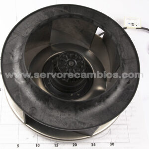
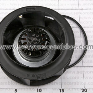
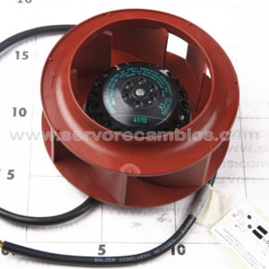
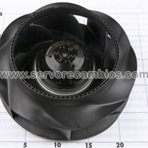
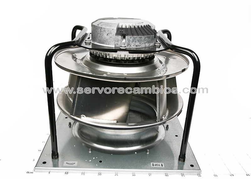
Model: K3G400-PW03-01
Motor: M3G112-IA
Electrical Data
Phases: 3~
Nominal Voltage: 400 V (range 380–480 V)
Frequency: 50/60 Hz
Performance
Speed: 2700 rpm
Power Consumption: 3400 W
Current Draw: 5.2 A
Operating Conditions
Ambient Temperature:
Min: -40 °C
Max: 40 °C
Note: Limited operation allowed down to -40 °C; continuous use below -25 °C requires special bearings
Mechanical Data
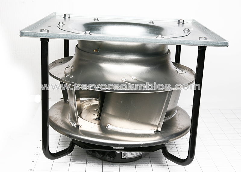
Weight: 25.1 kg
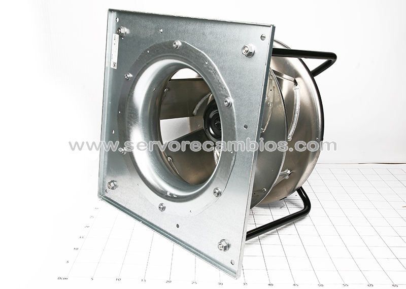
Fan Size: 400 mm
Motor Size: 112
Impeller: Sheet aluminum (5 blades)
Housing: Die-cast aluminum
Structure: Galvanized steel (support plate & inlet), painted steel bracket
Rotation: Clockwise (viewed toward rotor)
Protection & Construction
Degree of Protection: IP55
Insulation Class: F
Environmental Protection Class: H1
Motor Protection: Electronic protection
Features
Integrated PI controller
MODBUS RTU (RS-485)
Soft start & motor current limitation
Alarm relay & LED status indication
Configurable I/O
External control input (15–50 VDC)
Additional Information
Operating Mode: S1 (continuous operation)
Bearings: Ball bearings
Drain Holes: On rotor side
Electrical Connection: Terminal box
Protection Class: I (with protective earth)
Standards & Compliance
EMC: EN 61000-6-2 / EN 61000-6-3
Standards: EN 61800-5-1
Certification: CE