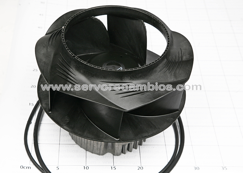
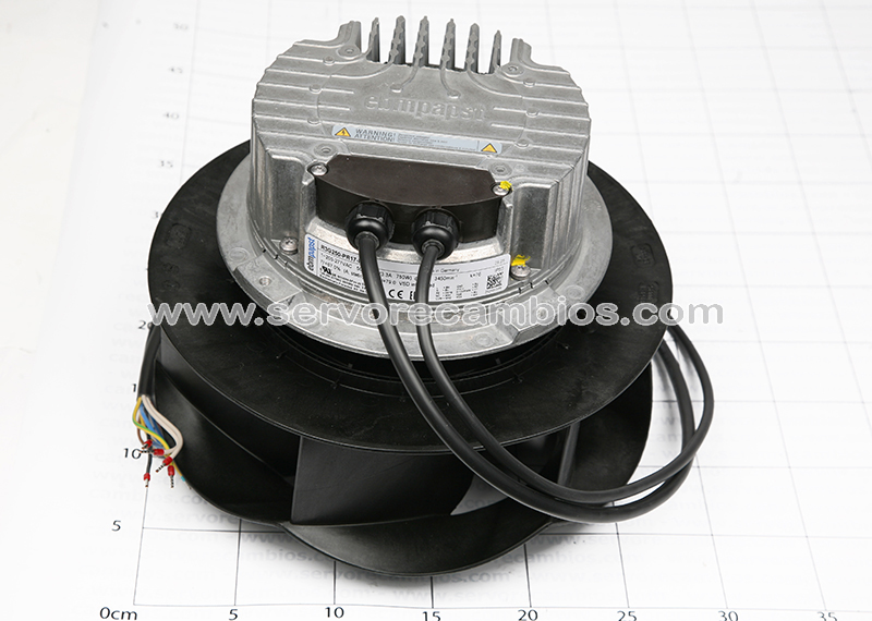
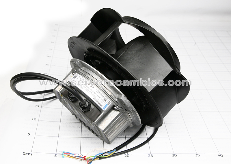
Type R3G250-PR17-I1
Motor M3G084-DF
Phase 1~
Nominal voltage VAC 230
Nominal voltage range VAC 200 .. 277
Frequency Hz 50/60
Method of obtaining data ml
Speed (rpm) min-1 3450
Power consumption W 750
Current draw A 3.3
Min. ambient temperature °C -40
Max. ambient temperature °C 45
Mass 4.683 kg
Size 250 mm
Motor size 84
Rotor surface Painted black
Impeller material PP plastic
Housing material Die-cast aluminum
Number of blades 6
Direction of rotation Clockwise, viewed toward rotor
Degree of protection IP55
Insulation class “F”
Moisture (F) / Environmental (H)
protection class H1
Ambient temperature note Occasional start-up at temperatures between -40°C and -25°C is permitted. For
continuous operation at ambient temperatures below -25°C (such as refrigeration
applications), use must be made of a fan design with special low-temperature bearings.
Max. permitted ambient temp.
for motor (transport/storage)+80 °C
Min. permitted ambient temp. for
motor (transport/storage) -40 °C
Installation position Shaft horizontal or rotor on bottom; rotor on top on request
Condensation drainage holes On rotor side
Mode S1
Motor bearing Ball bearing
Technical features – Output 10 VDC, max. 10 mA
– Operation and alarm display
– Alarm relay
– Integrated PID controller
– Power limiter
– Motor current limitation
– PFC, active
– RS-485 MODBUS-RTU
– Soft start
– Control input 0-10 VDC / PWM
– Control interface with SELV potential safely disconnected from the mains
– Thermal overload protection for electronics/motor
– Line undervoltage / phase failure detection
EMC immunity to interference According to EN 61000-6-2 (industrial environment)
EMC circuit feedback According to EN 61000-3-2/3
EMC interference emission According to EN 61000-6-3 (household environment)
Touch current according to IEC
60990 (measuring circuit Fig. 4,
TN system) <= 3.5 mA
Motor protection Thermal overload protector (TOP) internally connected
With cable Variable
Protection class I (if protective earth is connected by customer to the housing’s connection point)
Conformity with standards EN 61800-5-1; EN 60335-1; CE
Approval EAC; UL 1004-7 + 60730-1; CCC; CSA C22.2 No. 77 + CAN/CSA-E60730-1
Size 250 mm
Motor size 84
Rotor surface Painted black
Impeller material PP plastic
Housing material Die-cast aluminum
Number of blades 6
Direction of rotation Clockwise, viewed toward rotor
Degree of protection IP55
Insulation class “F”
Moisture (F) / Environmental (H)
protection class H1
Ambient temperature note Occasional start-up at temperatures between -40°C and -25°C is permitted. For
continuous operation at ambient temperatures below -25°C (such as refrigeration
applications), use must be made of a fan design with special low-temperature bearings.
Max. permitted ambient temp.
for motor (transport/storage)+80 °C
Min. permitted ambient temp. for
motor (transport/storage) -40 °C
Installation position Shaft horizontal or rotor on bottom; rotor on top on request
Condensation drainage holes On rotor side
Mode S1
Motor bearing Ball bearing
Technical features – Output 10 VDC, max. 10 mA
– Operation and alarm display
– Alarm relay
– Integrated PID controller
– Power limiter
– Motor current limitation
– PFC, active
– RS-485 MODBUS-RTU
– Soft start
– Control input 0-10 VDC / PWM
– Control interface with SELV potential safely disconnected from the mains
– Thermal overload protection for electronics/motor
– Line undervoltage / phase failure detection
EMC immunity to interference According to EN 61000-6-2 (industrial environment)
EMC circuit feedback According to EN 61000-3-2/3
EMC interference emission According to EN 61000-6-3 (household environment)
Touch current according to IEC
60990 (measuring circuit Fig. 4,
TN system) <= 3.5 mA
Motor protection Thermal overload protector (TOP) internally connected
With cable Variable
Protection class I (if protective earth is connected by customer to the housing’s connection point)
Conformity with standards EN 61800-5-1; EN 60335-1; CE
Approval EAC; UL 1004-7 + 60730-1; CCC; CSA C22.2 No. 77 + CAN/CSA-E60730-1